Model 7149 16-Channel RJ45 Cat 6 Compliant A/B Switch with GUI, Simultaneous Channel Control, Cascade Functionality, and Ethernet Remote Port
Overview
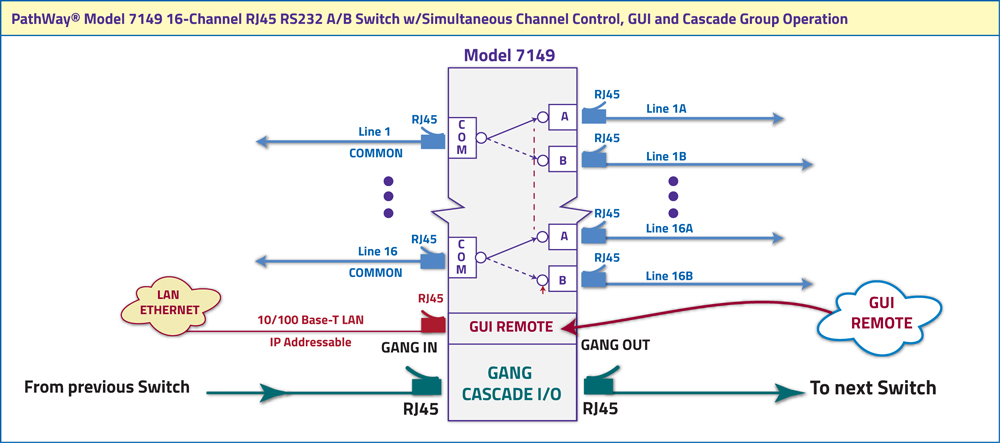
The PathWay® Model 7149 16-Channel RJ45 Cat6 A/B Simultaneous Channel Control, Cascade Functionality, and Ethernet Remote Port allows the user the capability of sharing a single port RJ45 interface device, connected to the “COMMON” port, among two other devices, connected to the “A” and “B” ports, for each channel. The Model 7149 is enclosed in a 2U, full rack size, all metal black chassis designed to provide EMI/RFI shielding and fit in a standard 19” rack.
The unit can be operated by either the front panel pushbuttons or the 10/100Base-T LAN Ethernet Remote.
The unit also supports gang operation, where multiple units can be connected and operated together in a synchronized fashion. The state of the unit can be obtained from the front panel LED’s or through the Remote Telnet Commands.
-
Gang Switch Sixteen Channels to an Alternate Path, Simultaneously!
-
IP Addressable!
FEATURES OF THE MODEL 7149 16 CHANNEL SWITCH WITH SIMULTANEOUS CHANNEL CONTROL:
- Supports (16) channels of A/B switch function
- All 8-pins of the RJ45 interface are switched
- Simultaneous control of all 16-channels
- Switch locally via (1) front panel push button; or remotely via an IP addressable 10/100 Ethernet remote port
- Local switch position control via (1) front panel push button, one button for all (16) channels
- Cascade group operation allows control of switch position and lockout as well as obtaining status of another unit connected to the cascade ports through the remote Graphical User Interface of a single unit
- Front panel LED indicators display switch position and power status
- The unit maintains last set position on power loss and continues to pass data
- Switch powers up in last known position
- Tested for Cat6 compliance
- All port located on the rear panel:
- (48) Shielded RJ45 female connectors for ports: (16) A, (16) B, and (16) COMMON
- (1)RJ45 female Ethernet 10/100 REMOTE port
- (2)RJ45 female GANG ports: (1) OUT and (1) IN
- Phoenix female port for power
- Rack mount enclosure, 19” Wide x 3.5” (2U) High x 10” Deep
- External 100-240VAC, 50-60Hz power supply included
TECHNICAL SPECIFICATIONS:
- SIZE (2U)
- Width: 19" (48.3 cm) (19" full rack size)
- Height: 3.5" (8.9 cm) (2U)
- Depth: 10.3" (26.2 cm)
- Weight: 8.27 lbs (4.3 kg)
- POWER REQUIREMENTS
- DC Voltage: 12VDC
- DC Current: 250mA (peak), 130mA (nominal)
- AC Power: 4W (peak), 3W (nominal)
- SIGNAL PORT INTERFACE:
- (48) RJ45 Signal ports
- (16) Channels of RJ45 A/B/COM ports
- Simultaneous Control
- REMOTE PORT INTERFACE:
- RJ45 female port
- LAN Graphical User Interface operation
- RJ45 (F) Cascade Port (In, Out) with Custom Pinout.
- Synchronous Group Operation
- FRONT PANEL CONTROL AND INDICATORS:
- (2) Red LED's
- (3) Pushbuttons
- POWER SUPPLY 517277:
- Input 100-240VAC, 50Hz/60Hz, 0.5A
- Output: 12VDC (regulated), 1.5A
Wide Range Power Option Available: (Cat No 517277) CE, RoHS and UL listed table mount power module, 100 VAC/240 VAC, 50Hz/60Hz for use in place of standard power module that is included with the unit. Has IEC 60320 C14 inlet. Ideal for international applications.
UTILIZING THE USER FRIENDLY REMOTE GRAPHICAL USER INTERFACE SOFTWARE
To connect to the switch from a workstation or computer having access to the LAN that the Model 7150 LAN port is connected to simply launch a standard web browser and type in the appropriate IP address.
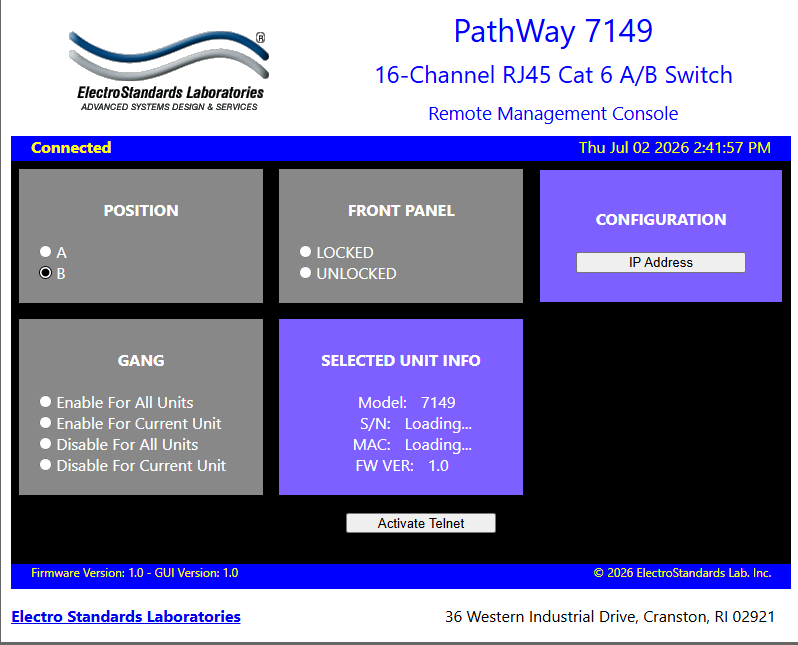
Figure 1: GUI in a Standard Web Browser
CHANGING POSITION AND LOCK STATUS
To change the switch position of a channel, click on the radio button “A” or ”B” as desired for all channels via gang controls. Locking and unlocking the front panel pushbuttons can be done by clicking on the “Locked” or “Unlocked” radio buttons for all channels. Gang Controls can be used to change the position or state of all channels simultaneously. When all channels are in the same position or state, that position or state will be selected by the Gang Controls. See Figure 2
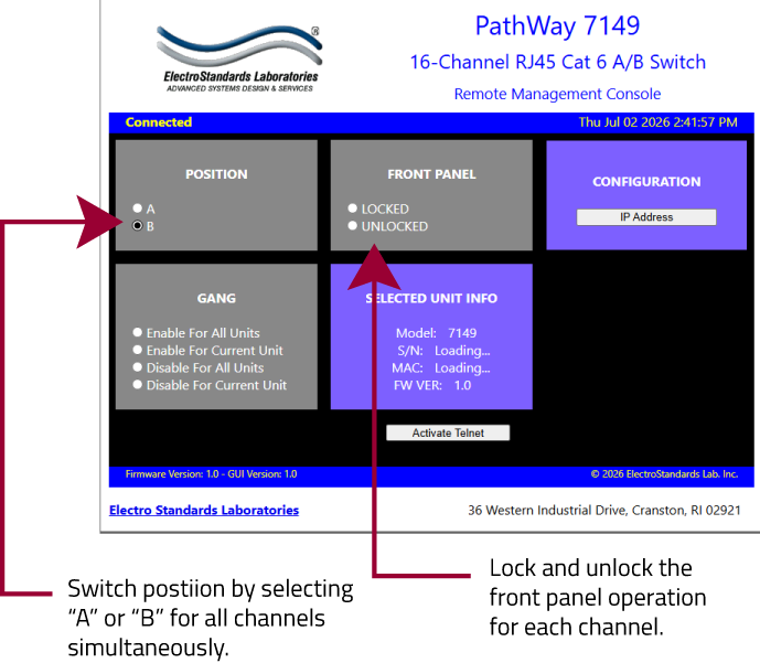
Figure 2: Change the position and lockout from the GUI
USING GANG CONTROLS
Gang Controls can be enabled or disabled for both the current unit, and well as any connected units via the GUI Interface. If enabled for all units, the user will be able to simultaneously control the switch position and lock state for every connected unit simultaneously. See Figure 3.
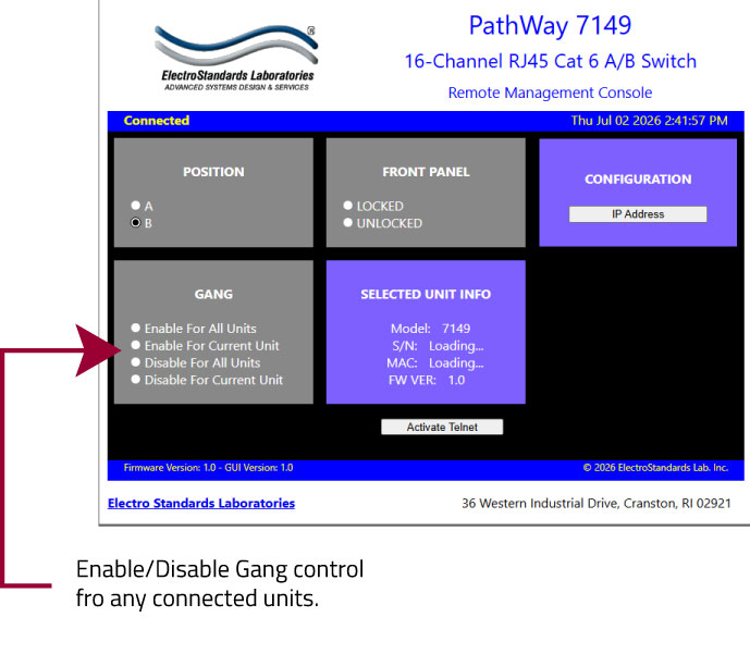
Figure 3: Using Gang Controls in the GUI.
Ordering Information
- Catalog Number: 307149
- Model Number: 7149
- Base Price: See website or contact us for current pricing and availability.
- Optional Wide-Range power supply: Catalog Number 517277 IEC C14 Inlet, 100-240VAC, 12 VDC
Documentation & Support
- Specification Sheet (PDF) Download Available.
- Product Manual available upon request.
- For custom fiber optic network switch requirements contact our sales support team 401-943-1164 or email eslab@electrostandards.com
- We welcome international inquiries and ship worldwide.
Shipping and Returns 
- Shipped via UPS ground (unless otherwise requested).
- Freight Charges prepaid and added to invoice. We can estimate freight charges for you.
- Return policy: contact us within 30 days of shipment for an RMA number. Items returned without RMA not accepted. Please refer to our full return policy in our Terms and Conditions found on our website.
Electro Standards can supply all of your Network Cable requirements.
For custom network switches call our friendly customer support staff at 401-943-1164, email eslab@electrostandards.com, or complete our online form: /Products-Custom/Copper-Switch/
All data switches, data communication products, and data acquisition products are subject to a one year warranty against manufacturing defects. The limit of ESL liability is limited to the cost of the ESL product provided.
*Prices online are subject to change and verification.
All ESL products are available for export.
Electro Standards welcomes International inquiries: commutateur d'ordinateur, equipo interruptor, interruttore del calcolatore, interruptor do computador, dator switch.