Overview

PathWay® Remotely Controllable Network Switch
Model 7364 Dual Channel Switch, DB9 A/B, DB9 Crossover with RS232, Telnet and GUI
SPECIFICATIONS:
- PORT CONNECTORS:
- (3) DB9 female connectors labeled A, B, and COM for Channel 1.
- (4) DB9 female connectors labeled A, B, C, D for Channel 2.
- CONTROLS: (2) Pushbuttons allow local switching.
- DISPLAY: (4) Front panel LEDs display switch position.
- TWO REMOTE CONTROL PORTS:
- (1) DB9 female connector on rear panel accepts ASCII RS232 Serial Data.
- (1) RJ45 female connector on rear panel accepts 10/100Base-T LAN Ethernet that uses both TELNET commands and GUI Interface.
- POWER: UL approved 120VAC-240VAC, 50Hz-60 Hz wall mount power module supplies 12 VDC, 500mA to the unit. Has 2-prong, US, non-polarized plug.
- DIMENSIONS: Rackmount configuration 19.0" W x 1.75" H x 8.0" D. (48.3 x 4.4 x 20.3 cm)
WEIGHT: Approximately 4.5 lbs. (2.0 kg)
PathWay® Model 7364 Dual Channel Switch, DB9 A/B, DB9 Crossover, with RS232, Telnet and GUI:
- The drawing illustrates two independent DB9 channels:
- Channel 1 is an A/B Switch.
- Channel One has a device connected to its COMMON port accessing two other devices connected to the DB9 A and B ports.
- Channel 2 is a Crossover Switch.
- Channel Two is a DB9 Crossover Switch allowing four devices to be in NORMAL or CROSSOVER position.
- There are two remote controls:
- DB9 RS232 serial data remote (ASCII RS232 Commands)
- RJ45 10/100 Base-T LAN Ethernet Access. (Telnet Commands or GUI Interface)
- The user can control the switch remotely from simple Point and Click software via the RJ45 port.

FEATURES:
- Unit allows independent switch control of two channels.
- Channel one is a DB9 A/B Switch. Channel two is a DB9 Crossover Switch.
- Independently control each channel remotely via either the DB9 Serial REMOTE port, or the 10/100 RJ45 Ethernet REMOTE port.
- Serial REMOTE port supports ASCII command set that allows position control, query of switch position, and front panel pushbutton lock/unlock.
- Ethernet REMOTE port commands include position control, query of switch status, and front panel lock/unlock. Unit password / login required to maintain security. Communicate with switch via TELNET.
- Remote control allows gang commands (simultaneous switching of both channels).
- All 9 leads are switched via break-before-make electromechanical relays.
- LED's display switch position.
- Switch maintains position and continues to pass data during power loss.
Channel 1 of the PathWay® Model 7364 Switch allows the user the capability of sharing a single port interface device connected to the COMMON port among two other devices connected to the A and B ports.
Channel 2 of the PathWay® Model 7364 allows the user the capability of attaching four devices connected to the A, B, C, and D ports in either a Normal or Crossover configuration.
Normal position is defined as port A connected to port C and port B connected to port D. Crossover position is defined as port A connected to port D and port B connected to port C.
Remote Control access may be accomplished using an Ethernet 10/100Base-T connection and either Telnet commands, or the Graphical User Interface.
The unit can also be controlled via RS232 ASCII commands through the rear panel DB9 Remote Port.
OPTION: WIDE RANGE POWER MODULE
(Cat No 517277) CE, RoHS, and UL listed table mount power module, 100 VAC-240 VAC, 50Hz/60Hz for use in place of standard power module that is included with the unit. Has IEC 60320 C14 inlet. Ideal for international applications.
UTILIZING THE USER FRIENDLY REMOTE GRAPHICAL USER INTERFACE SOFTWARE
To connect to the switch from a workstation or computer having access to the LAN that the Model 7364 LAN port is connected to, simply launch a standard web browser and type in the appropriate IP address. The Java Applet will be automatically uploaded from the switch upon connection. The environment requirement for the GUI is Java 1.7 and above.
SOFTWARE FEATURES:
- Access User Interface via standard web browser.
- Easy to use, simple point and click operation.
- Remotely access to control or monitor the Model 7364
- Users can change the switch’s IP address.
- LAN access gives users across the LAN or over the Internet access to control if user network is configured accordingly.
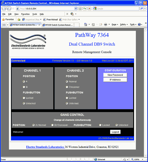
Figure 1: GUI in Standard Web Browser
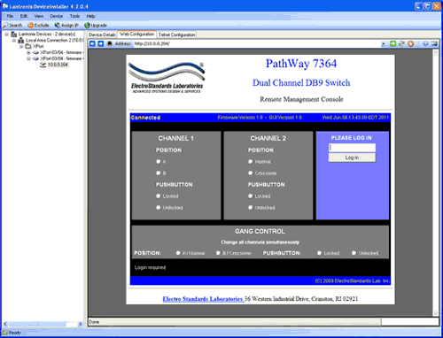
Figure 2: GUI in DeviceInstaller.
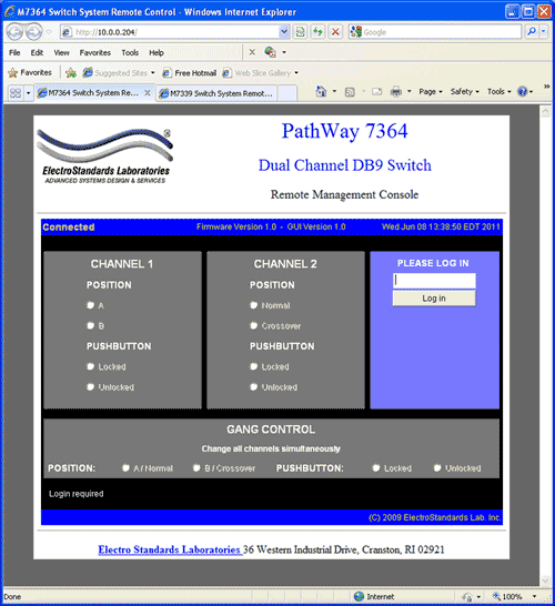
Figure 3: Logging into the GUI.
LOGGING into the GUI
- Once logged in, a user can perform one of any one of the following actions:
- Change the switch position
- Lockout control of the switch’s front panel
- Change the login password
- Re-configure the switch’s IP address

Figure 4: Change position and Lock Status.
CHANGING POSITION AND LOCK STATUS
To change the switch position of a channel independently, click on the radio button for "A/Normal" or "B/Crossover", as desired for each channel. Locking and unlocking the front panel pushbuttons independently can be done by clicking on the "Locked" or "Unlocked" radio buttons for Each channel. (See Figure 4).
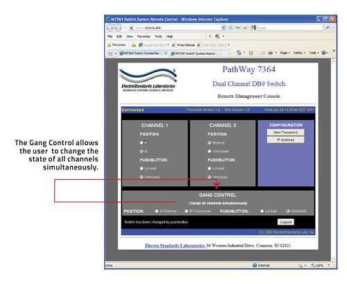
Figure 5: Change position and Lock Status simultaneously via Gang Commands changing the state of both Channels.
USING GANG CONTROLS to simultaneously Change the position of all Channel simultaneously.
Gang controls can be used to change the position or state of all channels simultaneously. When both channels are in the same position or state, that position or state will be selected by the gang controls. If one of the channels is in a different position or state, that respective gang control will not have either option selected. See Figure 5.
Electro Standards can supply all your Network Cable requirements. Click here to reach our CABLES, COPPER NETWORK Webpage.
For custom network switches call our friendly customer support staff at 401-943-1164, email eslab@electrostandards.com, or complete our online form: /Products-Custom/Copper-Switch/
All data switches, data communication products, and data acquisition products are subject to a one year warranty against manufacturing defects. The limit of ESL liability is limited to the cost of the ESL product provided.
*Prices online are subject to change and verification.
All ESL products are available for export.
Electro Standards welcomes International inquiries: commutateur d'ordinateur, equipo interruptor, interruttore del calcolatore, interruptor do computador, dator switch.
